 PHOTO2
![]()
PIXEL CARRIER (version
A)PIXEL_CARRIER_A (ppt)
This version is the first prototype of the PIXEL_CARRIER (6 layers Cu). The ladders are glued on the bus.
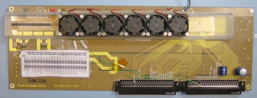 Pixel_carrier glued on interface card with
protection and fans (the chips are glued on the bus)
Pixel_carrier glued on interface card with
protection and fans (the chips are glued on the bus)
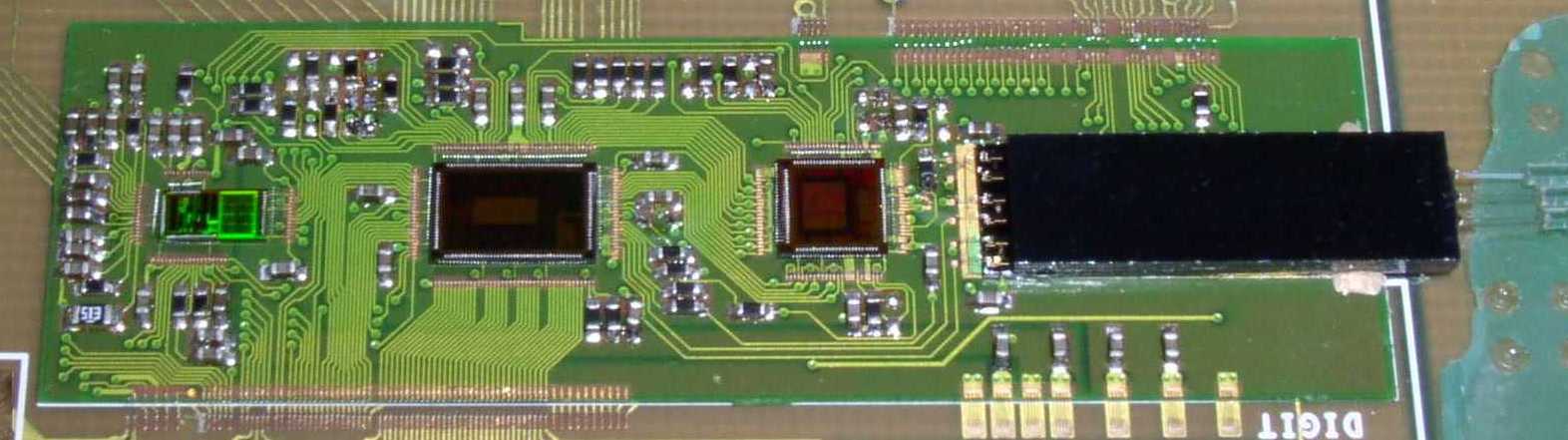
![]() The pixel carrier is glued on an interface card. 10 pixel chips are glued
and bonded on this carrier.
The pixel carrier is glued on an interface card. 10 pixel chips are glued
and bonded on this carrier.
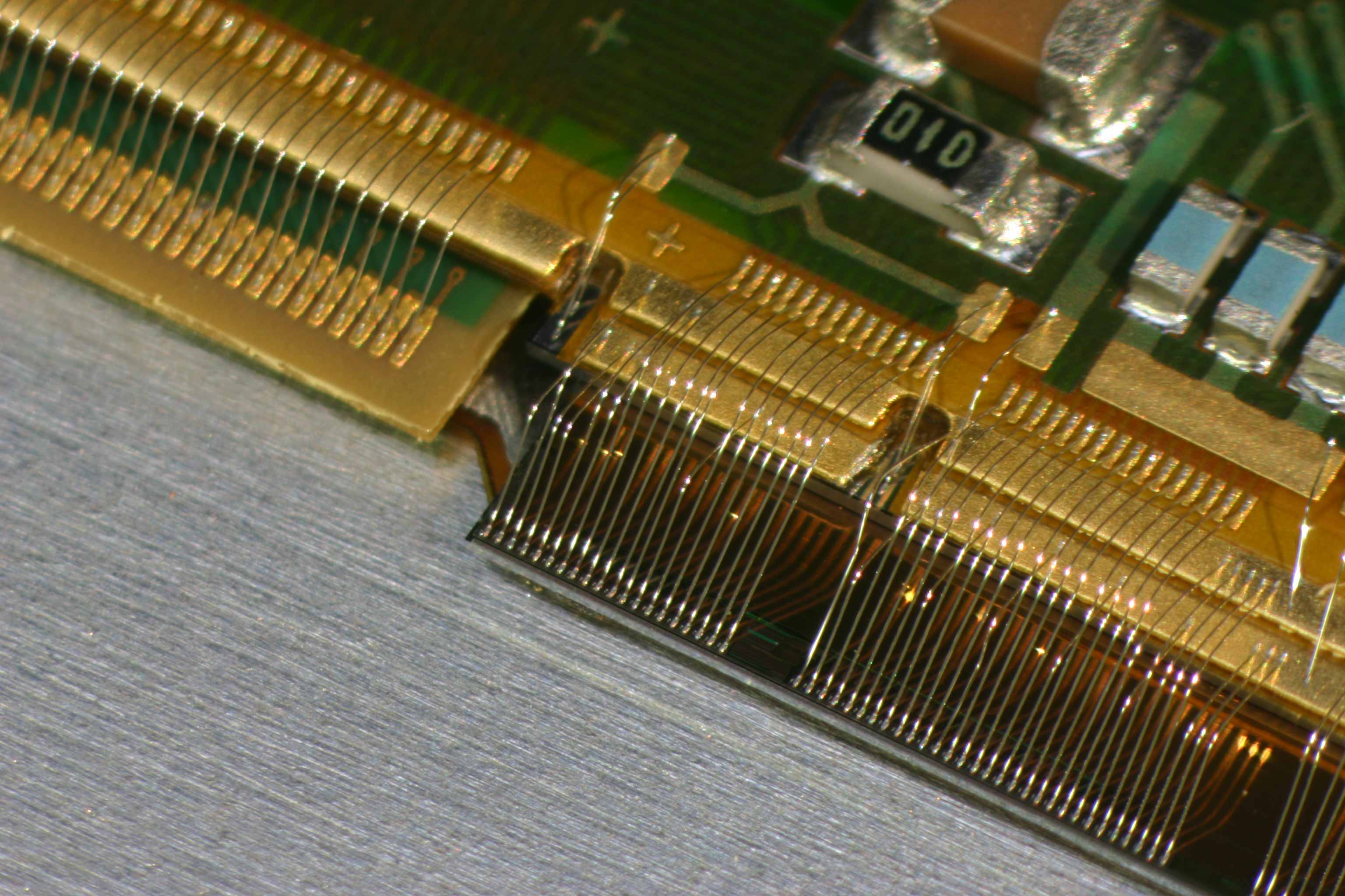
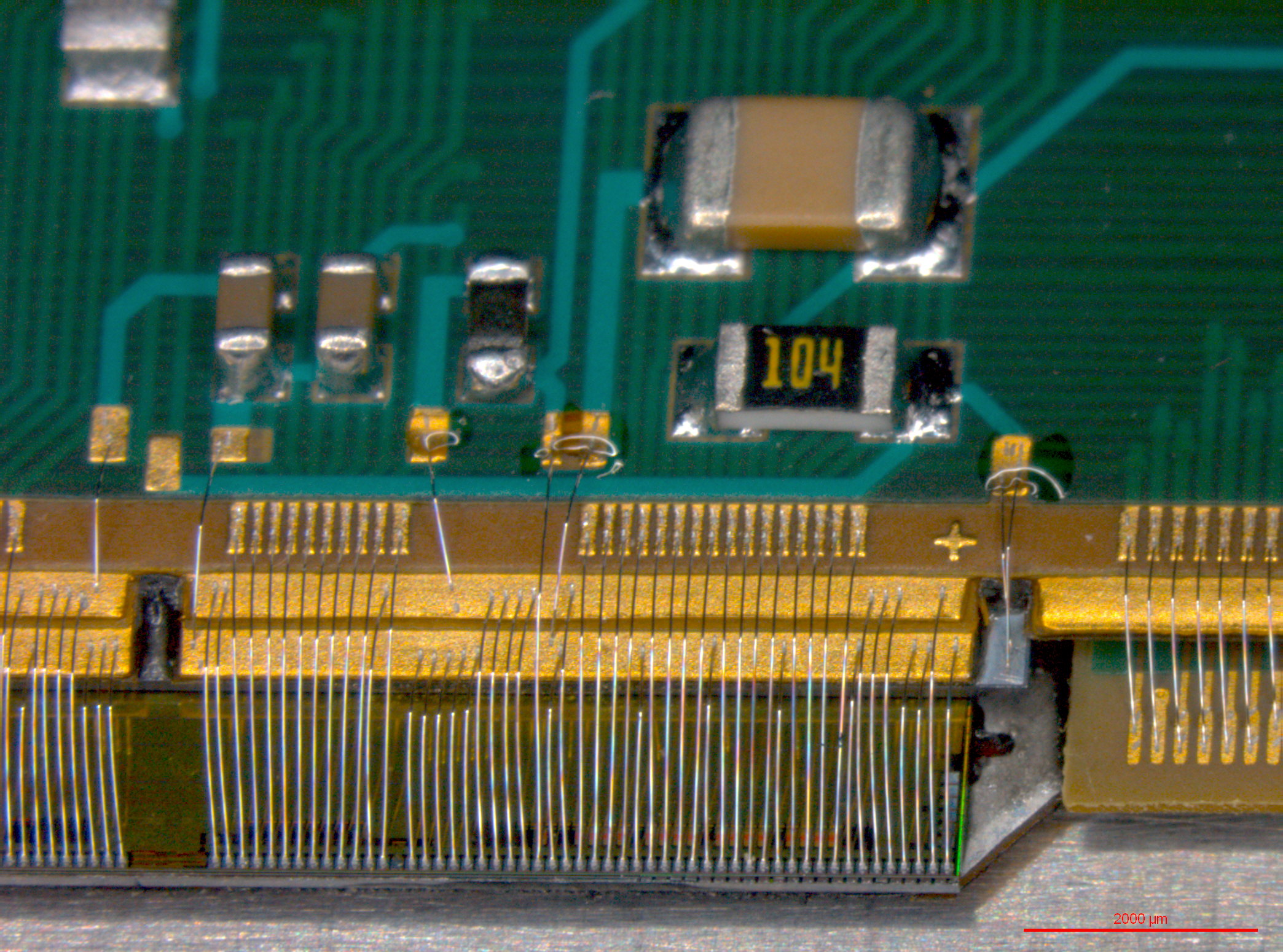
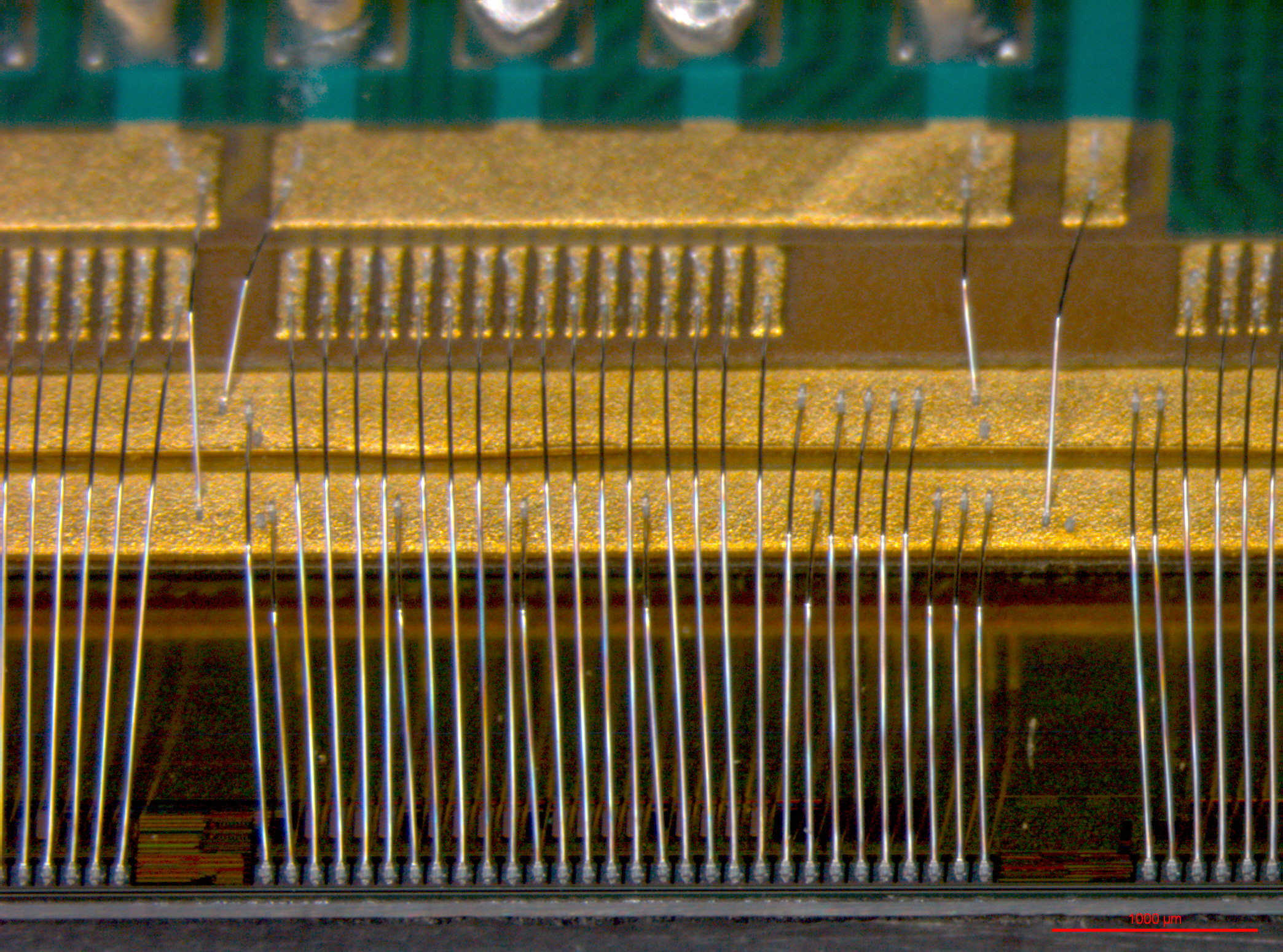
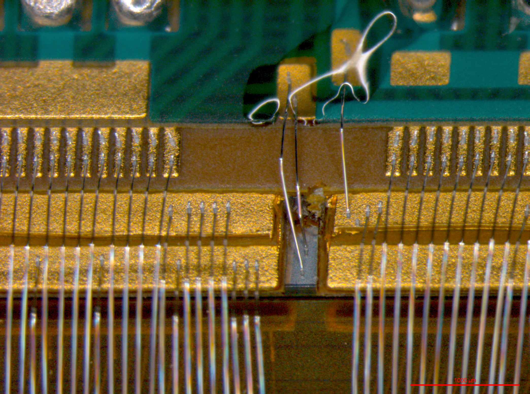
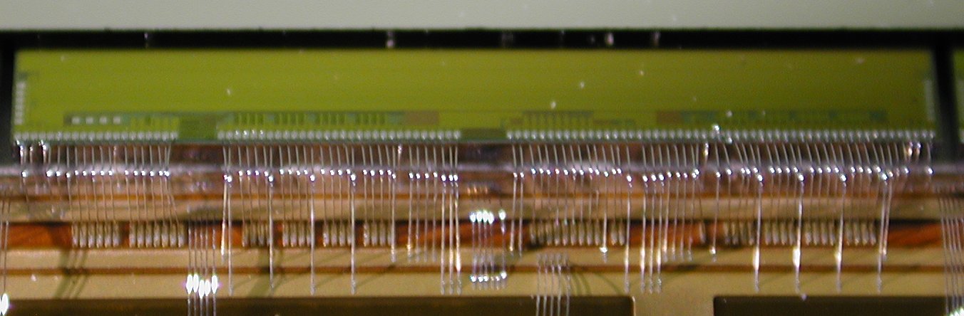 Detail
of a pixel_chip bonded on the
pixel_carrier
Detail
of a pixel_chip bonded on the
pixel_carrier
*** Click on the pictures to enlarge***
![]()
PIXEL CARRIER (version B)
This version is the second prototype of the PIXEL_CARRIER (4 power planes layers Aluminium ) and (3 signal layers copper).
Pictures: (click to enlarge)
![]()
![]()
![]()
![]()
7 layers Pixel bus mirror Pixel bus mirror (equipped with 2 ladders) glued on the interface
![]()
PIXEL BUS 2004
Mechanical Pixel bus and Pilot MCM drawings 2004 (pdf)
Details between Bus & MCM (pdf)
![]() Picture of
Pixel bus 2004 glued on the Ladders
(2 Al power planes + 3 Cu signal layers)
Picture of
Pixel bus 2004 glued on the Ladders
(2 Al power planes + 3 Cu signal layers)
![]()
PIXEL BUS 2005
Pixel bus and Pilot MCM 2005 (ppt)Last modifications on the bus and MCM
How it is done? (document in french)
You can find details on https://edms.cern.ch/cedar/plsql/fullsearch.doc_search:
EDA-00332-V3 pixel bus Right
EDA-00427-V2 pixel bus Left
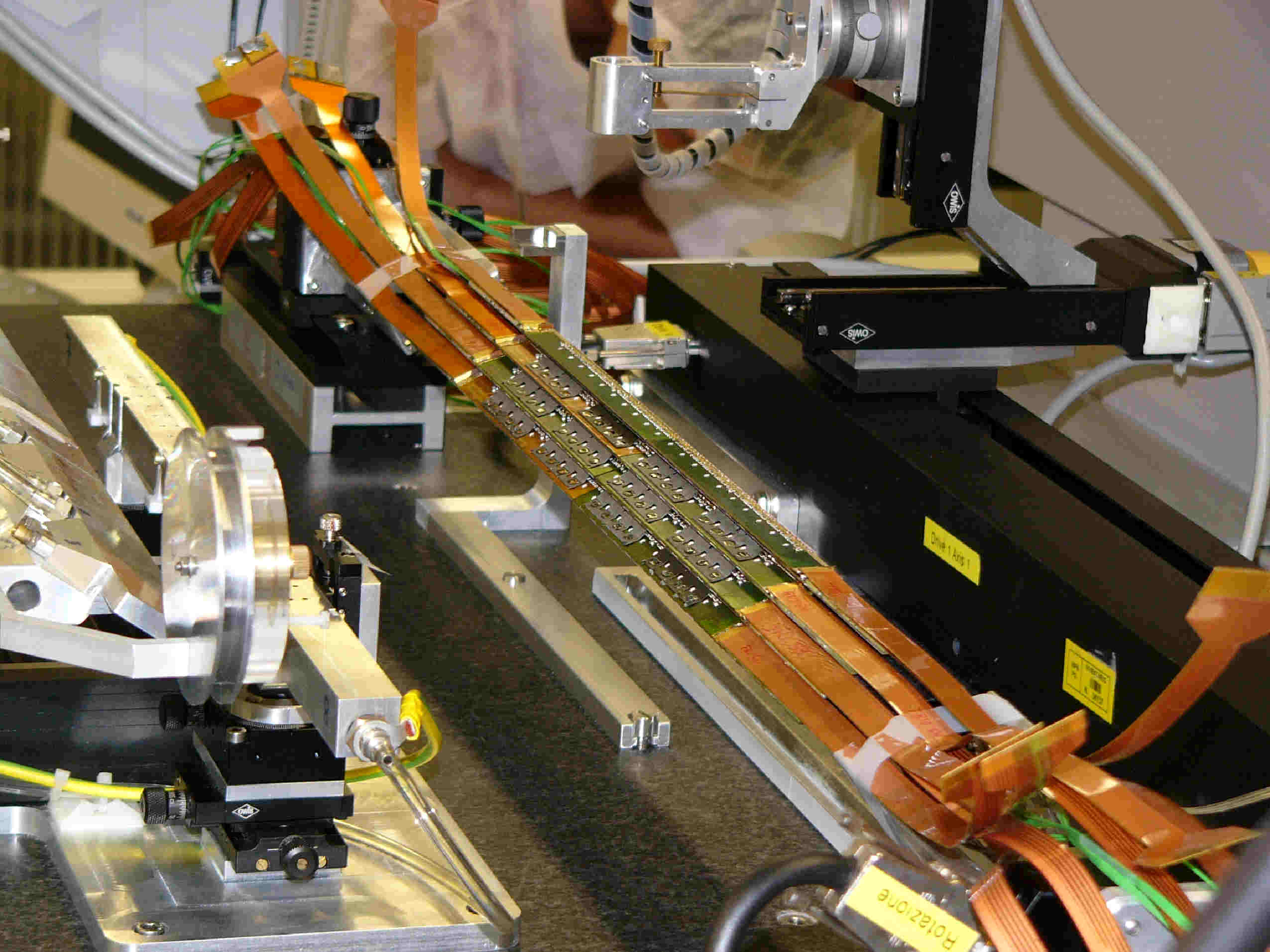
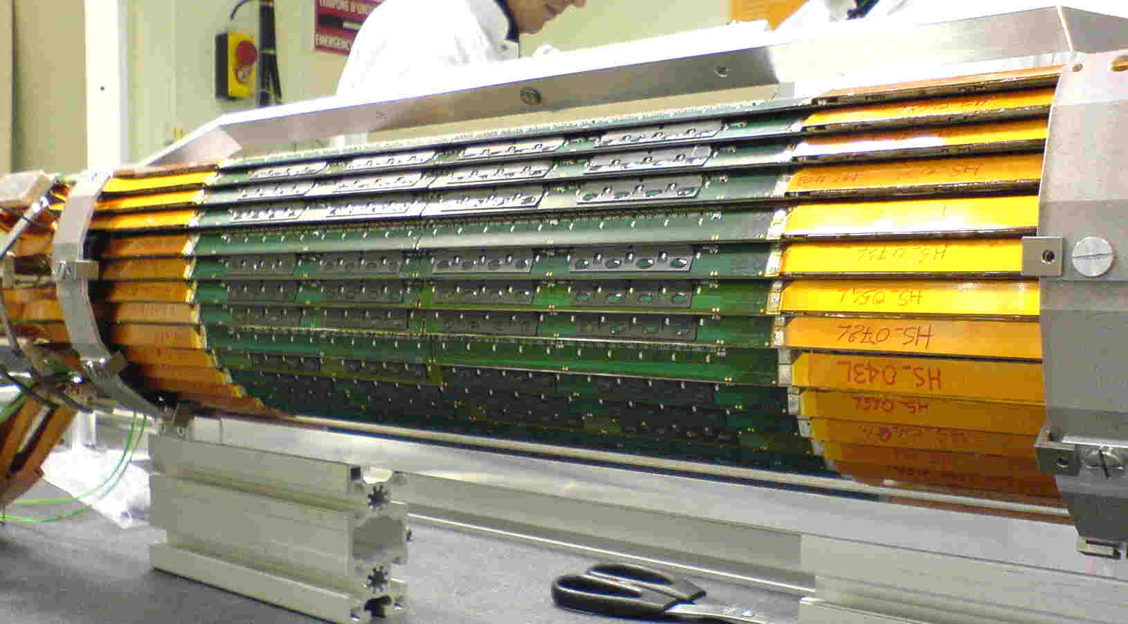
 Picture of Aluminium Pixel bus 2005 glued on the Ladders
and
connected
to MCM
Picture of Aluminium Pixel bus 2005 glued on the Ladders
and
connected
to MCM
![]()
PILOT MCM (FR4 version)
![]()
PI
LOT MCM (ceramic version)
![]()
PILOT MCM (SBU version)
![]() MCM right equipped with RX40 chip
MCM right equipped with RX40 chip
![]() MCM right with swapped between Digital Pilot
and GOL
MCM right with swapped between Digital Pilot
and GOL
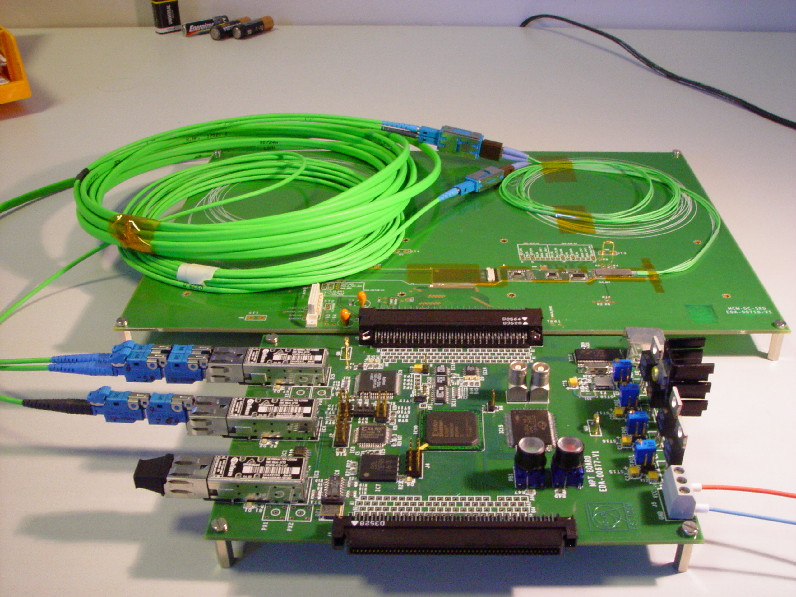 MCM right mounted on the test card connected to the MPT
Technical specifications of the SBU Pilot MCM
Details on EDMS
https://edms.cern.ch/cedar/plsql/fullsearch.doc_search: (In search window) EDA-00638 MCM Right or EDA-00732 MCM Left
MCM test results and location: mcm_test_results
PILOT_MCM production (.doc)
![]()
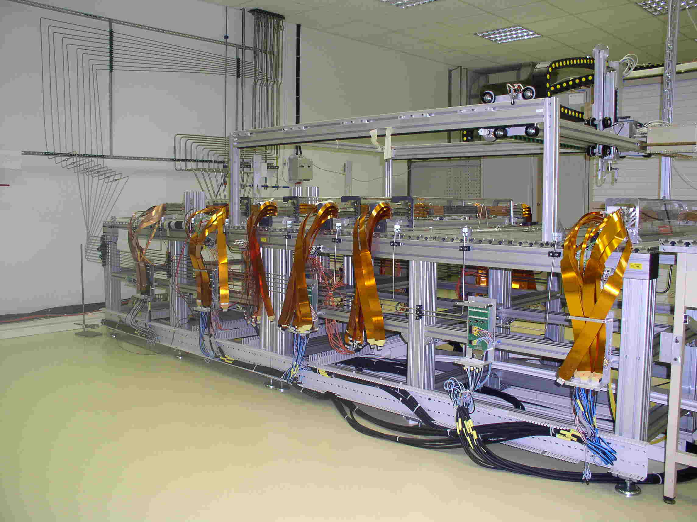
HALF_STAVES details
*** Click on the pictures to enlarge***
![]()
CABLES & PATCH PANELS
* SPD cable length and racks location
* SPD PATCH PANEL (location 0, 1, 4)
* SPD PATCH PANEL (location 2, 3)
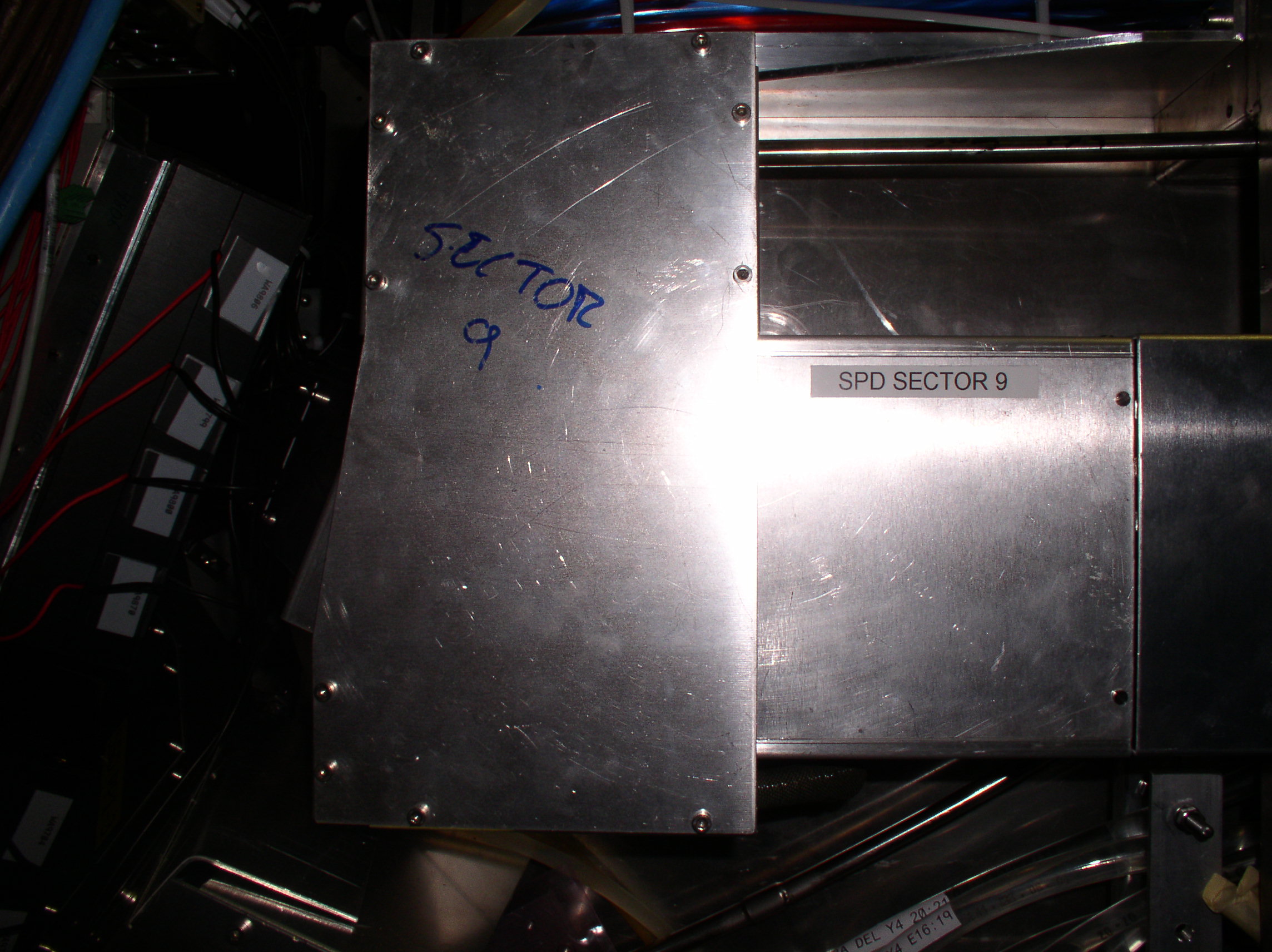
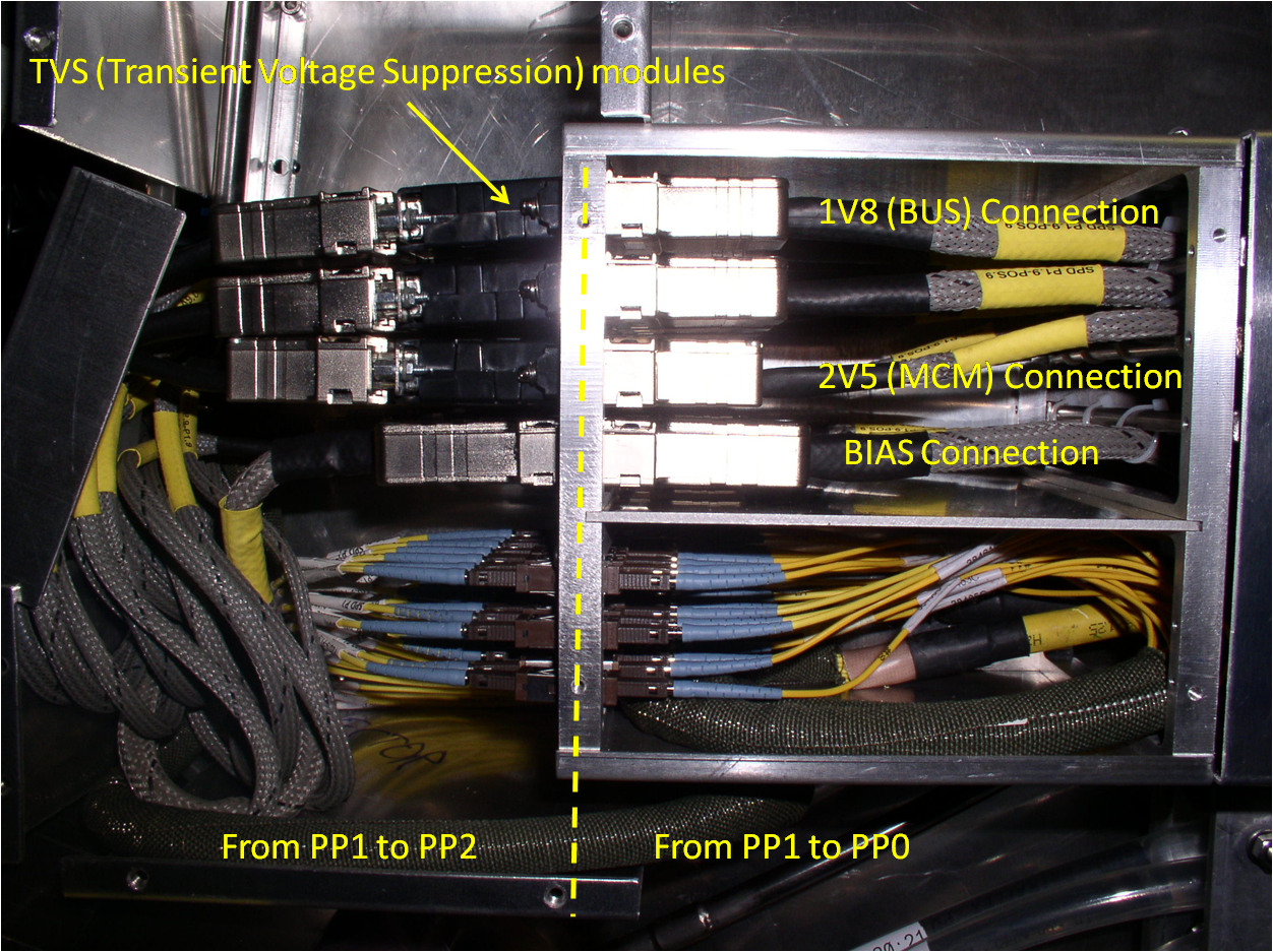
PP1 sector 9 Patch Panel closed PP1 sector 9 (Patch Panel is opened)
*** Click on the pictures to enlarge***
![]()
OPTICAL PATCH PANELS
* Optical Patch Panels (CR4 & PP5)
* Optical Patch panel (PP1 to PP2)
* Optical Patch Panels (PP0T under TPC)
* Glink measurements done in CR4 and |Trigger Crate (June 2008)
* Power margins measurements on side A (07/2009)
![]()
Humidity sensors placed under ITS
http://alicedcs.web.cern.ch/AliceDCS/monitoring/main.aspx
![]()
sectors in DSF
SPD in the PIT
![]()
List of the CAEN modules installed in the PIT
![]()